The Hackspace’s Many Moons
Not so long ago, walking through the hackspace at night was a dark and scary experience. Today, you’ll be guided by the hackspace equivalent of moonlight. You probably don’t know what I’m talking about… I am of course referring to the warm amber glow of an LED matrix display. Such displays have made many happy hackers all over the world. Early LED matrix displays were simple, typically built upon a string of shift registers – simple logic chips which take serial data and convert it to parallel outputs. Each output can be connected to one column of LEDs, and each row connected to some kind of current sink (or source, in some cases), such as an array of transistors. Due to their simple design, hacking them to do whatever you want is a fun and achievable project.
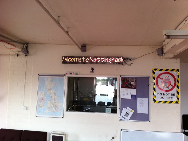
Like many hackspaces, Nottingham Hackspace has a long history of LED matrix displays. Our first dates back to 2011, hacked by Matt and set up ready for our first ever Open Day in May.
This display still runs today in our Comfy Area, showing emails to our, as well as messages posted from IRC and Discord using the display command.
Occasionally two or three of the left most modules go blank. It’s likely approaching time for a recap and some minor repairs.
Around the same time, if not the same time, Michael had managed to score an amazing donation for the space. Lots and lots of LED matrix displays! We still have many of them, although most of the “Big Clocks” were shared with other hackspaces around the UK, including Leeds Hackspace, London Hackspace, Build Brighton, and HacMan. This tradition of sharing displays between hackspaces still lives on, Limehouse Labs recently sent us four RGB 64×16 tiles, which I’m planning to install soon once I figure out what we should put on them!
In addition to the Big Clocks, there were also some smaller displays – one of which is what we called “Mini-Matrix”.
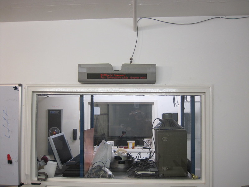
Mini-Matrix was hacked by Daniel in 2012, and like the big matrix, is still going strong. At start up, the display shows “BRB class 464”, so that’s probably a hint (although apparently a British Class 464 was a steam loco…).
At the time of install, that room was called the Blue Room. Since our expansion into downstairs, the room became the Craft Room.The display shows messages posted online using the display command, as well as who opened which doors.
A year or two after Mini Matrix was built, Daniel also built what we call the Laser Display. The main purpose of this display is to show who is booked onto the laser – now and next. If no one was booked on, you could hop and get a quick job cut before the next person, demonstrating that LED matrix displays can be both functional and stylish! The Laser Display lived for many years perched on a filing cabinet near the laser cutter. Sadly in 2022-2023 it had a nasty fall, and couldn’t easily be repaired (don’t worry though, we’ll come back to the Laser Display).
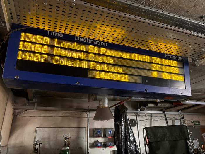
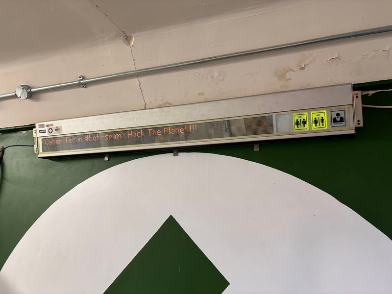
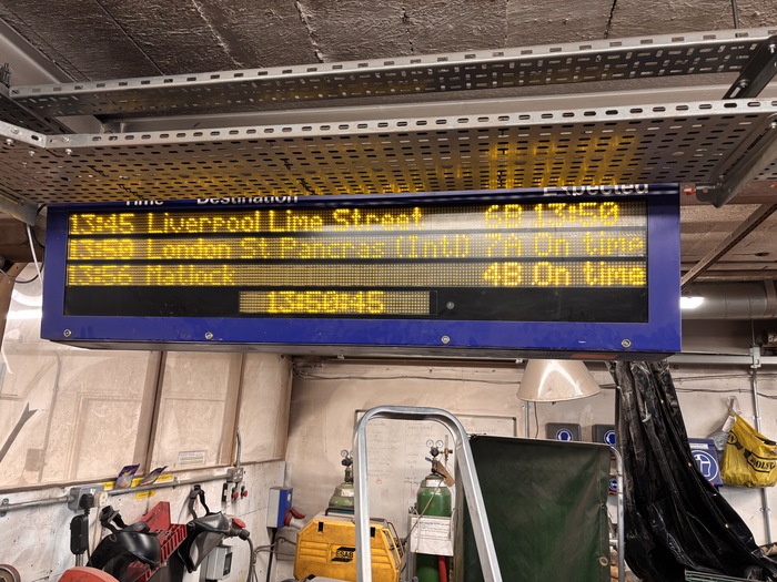
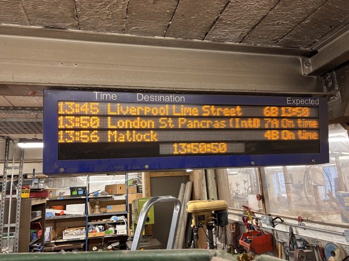
I joined Nottingham Hackspace in 2022 and for as long as I know, there’s been a real actual train departure board hanging from an I-beam in the workshop. Why was it not doing anything!? So many (one!) unanswered questions. I decided in 2023 that it should become a project of mine, and set about reverse engineering my first LED matrix display. I understood the basics, but after much trying was unable to get it to work. Eventually I realised that one seemingly unused pin was actually quite important, and drove the gate current so the brightness of the display could change depending on ambient lighting.
I was so happy when I got the display working. What a beautiful thing. I even cleaned the windows around the Dusty Area so that it could be seen from more angles.
The primary purpose of the display was to show messages in real time from our Discord, but given its original purpose, it would have been cruel not at least occasionally display a departure board. So, every 10 minutes, a Node RED flow pulls the current departures and pushes them to the display.
Another useful purpose of the display is to show which doorbell has been rung. The bell can be quite confusing – 1 ring for the front door, 2 for the inner door, 3 for the workshop door.
After the Train Departure Board, I worked on a few non-LED projects for a bit, but in 2024 I became very obsessed with LED matrix displays.
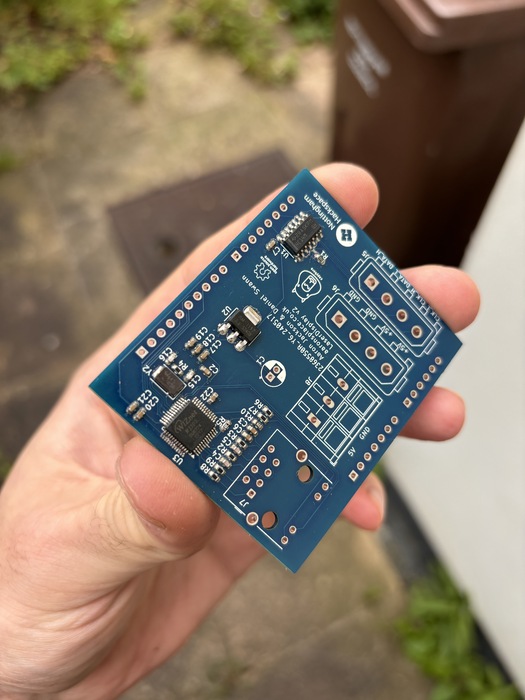
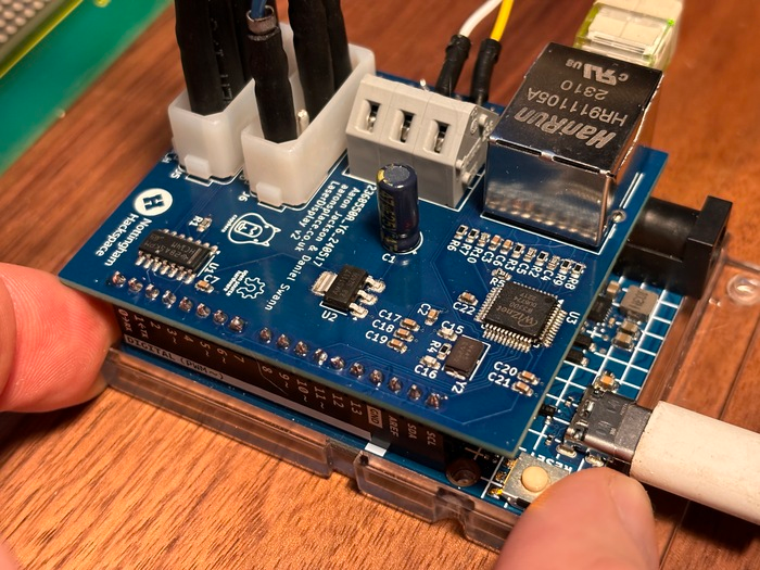
It was time to fix the Laser Display. The display wasn’t broken, but Daniel’s original perfboard was, so I decided to build a new one. The display uses quite an odd differential signalling to drive it, necessitating the use of logic gates to drive it from an Arduino. To make it a bit more interesting, I decided to try including a WizNet 5500 ethernet chip, which worked fine after some resistor value debugging.
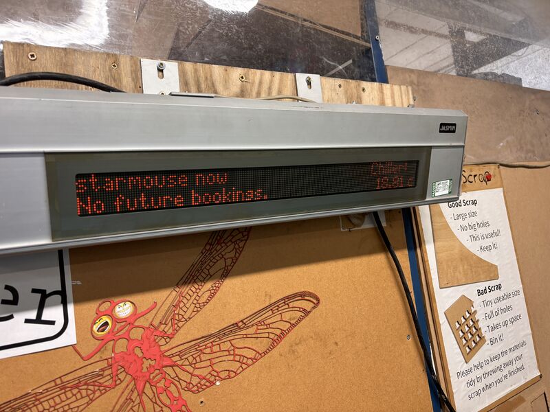
It now sits above the Laser Cutter, mounted to the wall, showing who’s on the laser cutter now and next, along with the chiller water temperature.
Displaying messages from Discord was too tempting, at least briefly after they’re posted.
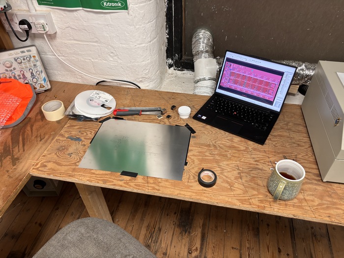
The Laser Display was also my first time doing an SMT board. It was fun learning about component sizes, laser cutting a solder stencil, populating a board (and possibly drinking some resistors) and reflowing on a hot plate. Here are some more pictures of the process. A huge thanks must go to Daniel for this one – he reverse engineered the display years ago and that saved me an enormous amount of time.
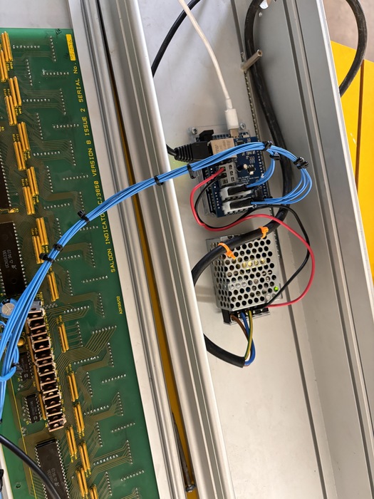
At this point we had: The big matrix, the mini matrix, a big clock (just hooked up to a radio clock), the laser display, the train departure board. Something was missing though. I knew what it was – it was a lack of LED matrix displays. The laser display was the smallest of three displays we have of the same type. The other two are much longer – one of which had been mounted in the Studio, but never used, and another, supposedly broken, in storage. I decided the next display should be in the Studio. Since the display used the same differential protocol as the laser display, it was quite easy to get working, and even used the same controller.
The display generally just shows messages from Discord, but since it came from a train, it felt appropriate to also show a two line departure board occasionally.
The lights on the right were something new. I had considered adding microswitches to the locks on the toilet doors, but thought people might find that a bit intrusive. Instead, the first WC light turns red when the Laser Cutter is in use, and the second when the Table Saw is in use (not that you can’t hear it anyway).
The service lamp is an easter egg left for members to figure out its purpose. Hint: it’s unironically in the name.
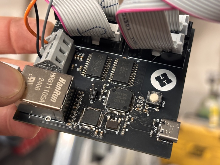
The LED matrix adventures weren’t over yet. I felt I’d learnt a bit about SMT and KiCAD with these projects, and I wanted to replace the board in the Train Departure Board. It was using the Uno R4 WiFi – yes, in a metal enclosure. It would occasionally disconnect, so I redesigned it to use Ethernet. I had originally intended to drive both sides of the display with the original board, but due to signal reflections along the ribbon cables, I could only get one side to work at a time. Adding buffers on the second version of the board solved this. Like the Laser Display, it included the WizNet W550 ethernet chip, and as a challenge, it included the Renesas RA4M1 instead of an Arduino. It worked!
The second version of the departure board was popular enough (on Mastodon atleast…) to end up in Hackaday – my first time! But anyway, I was pretty obsessed at this point, so it was time for another display. As mentioned earlier, we had another of these long “Laser Displays” which was apparently broken and in storage.

I got it out from storage and determined that two of the input logic gates had failed. Unfortunately I forget what they were, something in an SOP16 package, possibly NAND gates, but after replacing the display sprang to life.
Better late than never, the Electronics Area finally had its first LED matrix display. It runs the same code and does the same thing as the Studio Display.
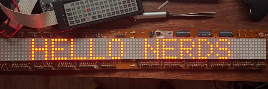
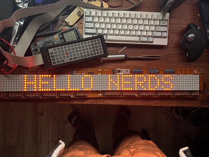
At this point, I was beginning to panic. We had legitimately run out of displays to hack on. I was entering what I call the “inter-project abyss” – a dark period of time in which I have nothing to obsessively think about. Prowling around eBay, I discovered a broken LED matrix display. I figured it couldn’t be that broken and managed to get it from < £10. It arrived and I managed to get it working pretty quickly using it’s built in keyboard. The internal battery had shorted, which was pulling down the logic voltage rails. Popping the battery allowed me to enter some text.
An obvious test message to share on IRC with my friends was “Hello nerds” – quite stylish I think. The display now sits above a door in my kitchen, since I truly believe that every kitchen needs an LED matrix display.
This one was hooked up to Home Assistant over MQTT and displays various sensor values from around my house. I used the Arduino from the Train Departure Board v1 and driving it was very simple.
As much as I love how amber it looks in this photo, the display is unfortunately a RED led display. No strong objections, but not my preference.
The inter project abyss was unfortunately rearing its ugly head again. After finding inspiration from a drawer in the Electronics Area, containing not one but at least 50 8×8 LED modules, I decided to solve the problem once and for all. I designed and built my own LED matrix display. The design is quite simple, some shift registers which can provide a decent amount of current, and a ULN2803 sinking current for which ever row I had selected. The board includes the Arduino chip (RA4M1 again), and a WizNet W5500 (again). Assembly requires some patience, it is necessary to place not only the 16 shift registers and 3 or so other chips (and their support components), but also 128 resistors. Steve rightly pointed out that I should have used some resistor arrays. With a bit of music, placing this amount of resistors turns into quite a meditative experience.
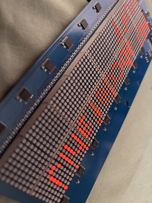
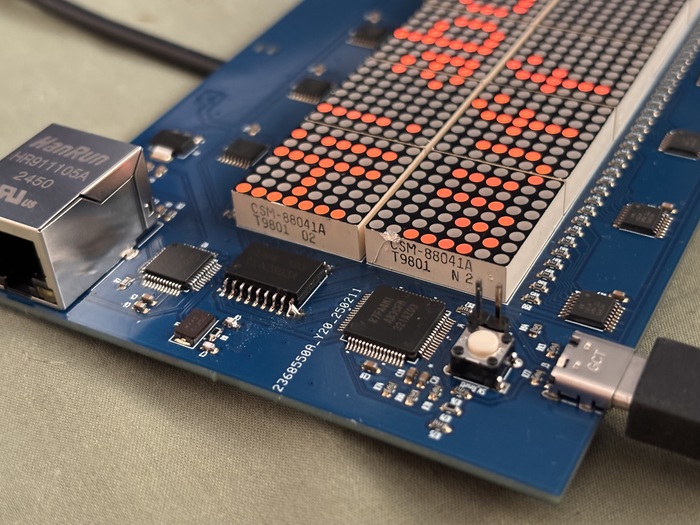
There was one small error where I’d forgotten to connect a pad to ground. A minor bodge results in it working quite well. Can you spot the bodge? With these displays I realised that I could stream video using ffmpeg. Finding exactly the right arguments was a bit problematic, but in short order I was watching a very red version of Contact on a 64×16 display. I’ve not put these displays into action yet, in fact I don’t really know what I want to do with them. Their main purpose was to satisfy my need for a project – I think this is true of all LED matrix displays being hacked around the world though.